
So you finally got sick of climbing behind your desk or wiggling under your rack to change your audio signals' path through your now giant recording gear collection. I don't blame you.
The dust, the spiders, the cat hair, and other surprises aren't worth the trouble, especially when there's an affordable and genius solution on the market.
Take into account that most of us end up unplugging three cables by accident for every one we successfully add and you can understand why a patchbay is a non-negotiable piece of equipment.
It doesn't matter if you manage to wire up your own bay or you bought one new (of all of the gear out there, this is the one you don't want to buy cheap or used due to the million parts that someone else likely broke), you will still need to know how to use it.
And it's not just a matter of being able to use one. You want to learn it right, because there is a correct way and this is the way all of the other professionals you'll encounter learned it.
Patchbays are becoming increasingly important due to the increased popularity of structured wiring, where commercial buildings and homes are built with cabling within the walls and flooring.
There is no rewiring in these cases so even the casual user is beginning to be confronted with the issue of using a patch panel.
Since collaboration and communication are critical for efficiently recording high-quality music and audio while the creative juices are flowing, nothing is more important than unraveling this mystery and putting it back together in our heads in the same way others have.
Before we get started, let me say that any newcomers to the concept of a patchbay should also read our article called The Best Patchbay for Studio & Live Audio.
The reason is that, before we review any specific models, we give a summarized run down of everything you need to know about these miracle machines, including how to use one.
In this article we're going to take a deeper look at the methodology. While still accessible for all levels of recording engineer skill, the examples and explanations will be far more involved, and we're going to assume you know what patchbays, patch cables, and jacks are as well as recording studio cable types such as TRS, XLR, TS, etc.
We'll proceed by narrowing down the possibilities (and reducing confusion) by laying out some ground rules, then give some tips to further help stay organized, explain the three modes each series of jacks can use, and then finally lay out an example with a walkthrough.

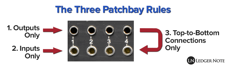
The Three Patchbay Rules
The first way to wrangle in all of the possibilities is to setup your patchbay in a manner that greatly reduces your options. In the same way, it brings you into alignment with other professionals and also keeps you organized.
This is done through observance of the three fundamental rules to setting up your patchbay:
- Top jacks are for outputs
- Bottom jacks are for inputs
- Connections only occur top-to-bottom
Let's discuss each of these in depth, even though they're self-explanatory, because it sets the stage for understanding the tips and discussion on modes below.
Rule 1 - Top Jacks are for Outputs
Always envision the audio signal going into the top back jack and coming out of the top front jack. The top jacks are called output jacks because the top back jack receives the output from whatever piece of gear you're using and spits it out of the front top jack.
If you follow this rule (as do all professionals) you will only be dealing with the outputted signal when you're patching the top row. In most cases (keep it simple for now), the signal comes out of the keyboard or microphone, goes into the top back, and comes out of the top front.
The outputs are top only, back-to-front.
Rule 2 - Bottom Jacks are for Inputs
So now you have your signal coming out of the top row on the front of your panel. You plug in a patch cable and route it to the bottom row, which is the exact opposite of the top row.
It is only for inputs on your gear. The signal flows into the cable, into a bottom front jack, and out of the bottom back jack and into an input in another piece of gear.
The inputs are bottom only, front-to-back.
Rule 3 - Connections Only Occur Top-to-Bottom
Since outputs are on top and inputs are on bottom, you will never need to or want to patch a cable from a top jack to another top jack. The same goes for bottom to bottom connections. They don't happen.
Patch cables only ever connect a top jack to a bottom jack.
These three rules set the stage for making a patchbay useful. Otherwise it'd be pure pandemonium.
Never stray from these three rules or you'll defeat the purpose by having to climb behind your rack to figure out how the heck you cabled all of your gear in. The above rules and the tips below will make sure you never are stuck wondering what goes where.
Patchbay Organization Tips
By restricting the top jacks to outputs and bottom to inputs, you've minimized the chaos big time. But there's still a lot of room for confusion and lost time. Here's a few more tips that will ensure your patch panels are doing what they're meant to do: save you time.
Label Your Jacks: Before all others, this is the most important. The smallest patchbay you'll use is likely a 48-point panel, meaning you have that many jacks to try to remember. You won't be able to remember, so you need a labeling system. Some bays have dry-erase strips you can write on across the front.
If not, you can write on the top part of sticky notes and stick them on there. My favorite method is to create a software spreadsheet I can easily re-label. I keep mine printed out in a desk drawer, ready to be referred to at any time.
Only Patch What You Use: If you don't mind buying several bays, then you can disregard this but for those who only have one or two, it's important to only connect what you use regularly. This reduces the options in the bay, which in turn reduces mistakes
It's better to have your most frequently used recording gear together than spread out amongst a ton of crazy effects pedals and other stuff you never use. If you do purchase more than one, designate one as your main patchbay and then have a secondary and tertiary one.
Forget About the Order: This tip may seem like it contradicts the one above, but it doesn't. You'll have your gear grouped by frequency of use, but other than that don't worry about concepts like keeping your preamplifiers together.
Because what happens is you'll get a new piece of gear... are you really going to rewire your entire bay just to slide everything down by one jack so your compressors can be next to each other? This is why we label the jacks! Group by how often you use them, not by type.
Don't Match Top-to-Bottom: This is a typical rookie mistake that stems from not knowing how to use the three main modes (as discussed next). People tend to want to have the output and input of a piece of gear stacked vertically, but that's actually not the most efficient way to use a patchbay. We'll look at why in the next section.
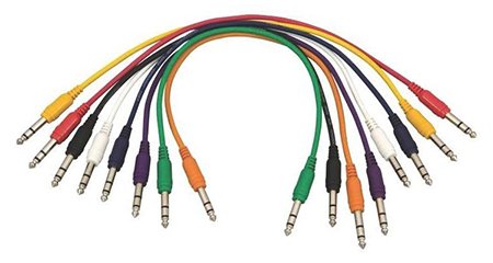
Use Short, Color-Coded Patch Cables: The next best thing you can do for organization is to use short, color-coded patch cables. These tend to come in the seven colors of the rainbow, plus white, black, and gray. So you can divide the possible number of inputs and outputs you're trying to trace down by 10 when you're wondering where each cable leads.
Some people tape paper labels or use colored rubber bands wrapped around the jacks, but that doesn't help you quickly visually identify where the cable is going. Colors, on the other hand, are a piece of cake. Also, if you use the least length possible, you'll have that much less jungle behind your rack.
Now that you're organized on the exterior of the patchbay, let's see what we can do on the interior by changing the modes of the jacks.
Normal, Half-Normal, & Thru Modes
We just resolved a lot of confusion, but we're about to add some back. Once it makes sense for you, it actually reduces the chaos and makes your bay faster to use. There are three ways the jacks are wired together that represent the three main modes of usage.
Some patchbays let you change modes with a switch. Some require you to physically manipulate the jacks. Some don't let you change the mode.
It's fine, though. You can stick with Normal mode and be perfectly happy, you'll just need more patch cables. But if you learn to use the other two modes you can really dial in the magic to save you effort and cabling time. Let's discuss each mode:
- Normal Mode: The top output jack sends the audio signal to the bottom input jack until a patch cable is inserted. The cable interrupts that signal path and intercepts it, sending it through the cable only.
- Half-Normal Mode: The top output jack sends the audio signal to the bottom jack even if you've inserted a patch cable. This lets you split the signal to send to two inputs. The splitting will be interrupted if a cable is patched into the front input, though.
- Thru Mode: The top output jacks only sends the signal to each other, back-to-front. Unless you plug in a cable to send the signal to an input, the signal hits a dead-end.
For the most part, Normal Mode and Half-Normal mode will take care of all of your needs.
Most of us hang out in Half-Normal Mode, where we record and do simple mixing and clean-up equalization work out of the box and then send the signal to the interface, where we finish up the mixing in the box (meaning in a software, preferably one of the best DAW's like Pro Tools or Logic Pro).
We can then pass back out of the box if we like. Half-Normal is preferred because you can use it like a send to an auxiliary bus on a mixer. It's the most complicated to understand, but once you have it in your head, you're good to go.
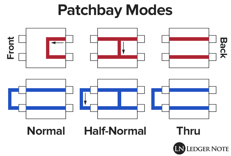
Most newcomers envision the jacks as working in Thru Mode by default, but that's not the case.
So why is Normal and Half-Normal even a thing? Why are they useful? That can be explained by walking through an example set-up, which we have below.
Example Patchbay Setup & Walkthrough
We're going to walk through a simple set-up only using an imaginary 12 point patchbay. If you can wrap your head around 12 points, you can deal with as many as you want. The key is to be able to trace the signal out and in, out and in, through the jacks and your gear.
Let's forget about Thru Mode, because it's self-explanatory. We'll place the first three set of jacks (top and bottom) in Normal Mode and the second set of three in Half-Normal Mode.
First, take in a quick overview of the table below, which represents our patchbay turned on it's right side and all cabled in and ready to go, with the front and back both visible for explanation's sake.
| Panel | Top Back (Output) | Bottom Back (Input) | Top Front (Output) | Bottom Front (Input) |
|---|---|---|---|---|
| 1 (Normal) | Keyboard | Mixer Input 1 | N/A | N/A |
| 2 (Normal) | Reverb | Mixer Input 2 | N/A | N/A |
| 3 (Normal) | Compressor | Mixer Input 3 | N/A | N/A |
| 4 (Half-Normal) | Mic Preamp | Reverb | To 5-Bottom | N/A |
| 5 (Half-Normal) | N/A | Equalizer | N/A | From 4-Top |
| 6 (Half-Normal) | Equalizer | Compressor | N/A | N/A |
Let's say you're a solo singer-songwriter with a digital piano and some vocals. You've got this patchbay setup on stage with you in your mini-rack so you can do the mixing yourself so the sound guy can't butcher your performance.
So you have two main inputs: your keyboard and your voice through a microphone. Your keyboard has weighted and pressure sensitive keys so you don't worry about mixing it. You dial in a little reverb on-board and forget about it. What you want to work on is your vocals.
Dealing with the keyboard is easy. You run its output into Top Back 1. Since you won't be routing the signal anywhere else, you won't plug in a patch cable.
And since the first set of jacks is in Normal Mode, the keyboard's output signal flows right down to the Bottom Back 1 automatically and then through the cable into the mixing board's first input. That is the magic of Normal Mode, versus Thru Mode which would have required an extra patch cable for no good reason.
Vocals are trickier because you want to accomplish two things. First you want an uncompressed, non-equalized version of your vocals to run through a reverb unit to simulate your dynamic range for the listener. It's more realistic and intimate this way.
But you want your "main take" to run through a compressor and be squashed like a bug so everyone can understand you. But first it needs to run through your EQ for a little clean up action. To make matters worse, both versions have to come from the preamplifier!
So first things first, you run the XLR from your mic into the preamp. The preamp's output is cabled into Top Back 4. The fourth set of jacks is in Half-Normal Mode, which means you can split the signal. It will flow into whatever is cabled into Bottom Back 4 and wherever you send it with a patch cable.
For this reason, we have the reverb effects processor accepting input from Bottom Back 4. We have the reverb unit's output leading to Top Back 2, which is in Normal Mode, so it automatically drops the signal to Bottom Back 2 which leads to the second input of the mixer. Done.
But we still want to EQ and compress a version of the output from the preamp. So we run a patch cable out of Top Front 4. This splits off of the pre-reverb version of the vocals. We take this output and use a cable to send it to Bottom Front 5, which leads right out of the back into the equalizer's input.
We do our EQ work there and see that the output of the equalizer is leading to Top Back 6. The sixth set of jacks is in Half-Normal which drops the signal to the output below no matter what, so we don't even need a cable to hit the input of the compressor, which is cabled from Bottom Back 6.
All we have to do is run the output of the compressor to Top Back 3 and it drops automatically into the third mixer input. Our job is done and we let the sound guy adjust the levels.
One final thing, though, is that we want to handle our own mix for our on-stage monitors. We goofed. Had we set the first three set of jacks to Half-Normal Mode we could have run an output to our own personal 3-track mixer and outputted to the monitors there.
Maybe next time! Even if we wanted to do this, we managed to only need one patch cable for the entire process. That's what having a properly organized patchbay in your rack is all about.
And That's How to Use a Patchbay
Using the guide above, you may be able to vastly simplify and understand the complexities of a patchbay much better. If you're here reading this, it may be the case that you already have access to a bay.
But you may still be on the hunt. Take the time to peruse our reviews of the best patchbays in various price ranges (you can skip the top portion which is largely a summary of this post).
In the end, it may take some experimentation or looking at another tutorial to fully manipulate these monsters, but once you know how to use a patchbay the right way, things will never be the same.
You'll never have to stop yourself and break your flow while in u0022creative modeu0022 to jump into u0022technology modeu0022 in order to cable up some gear. Patch those suckers in on the fly and keep rocking. Thanks for reading our patchbay guide!
Jared H.
 Jared has surpassed his 20th year in the music industry. He acts as owner, editor, lead author, and web designer of LedgerNote, as well as co-author on all articles. He has released 4 independent albums and merchandise to global sales. He has also mixed, mastered, & recorded for countless independent artists. Learn more about Jared & The LN Team here.